


Fluke Indonesia (2)
Fluke Indonesia
Fluke Indonesia - Temperature transmitter calibration
PT. BEST INSTRUMENT INDONESIA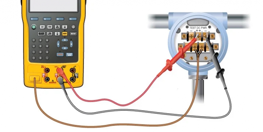
Fluke Indonesia - Temperature transmitter calibration
The performance of temperature transmitters and related instruments can decline, especially in the harsh environments found in industrial settings. Temperature transmitter calibration maintains reliability and uptime.
Fluke calibrators, such as the Fluke 724 Temperature Calibrator or the Fluke 754 Documenting Process Calibrator, can provide the three things necessary to accurately calibrate a temperature transmitter – sourcing temperature, providing loop power and measuring the resulting output current.
Most advanced documenting process calibrators, such as the Fluke 754, can also test and calibrate both temperature and pressure instruments, which keeps the number of instruments a technician needs to carry to a minimum. The 754 can even calibrate the most-used tasks of HART electronic instrumentation, including pulsed instruments such as RTD transmitters. A calibrator combined with a dry well such as the Fluke Calibration 9142 Field Metrology Well provides a complete closed-loop solution.
When comparing calibrators, the traceability of test equipment is also an important factor. Traceability means the calibration’s test and measurement functions have been verified to perform within required specification and those specifications are traceable to national and international standards. All Fluke test equipment can be ordered with a NIST-traceable calibration.
Fluke Indonesia - How to Measure Resistance with a Digital Multimeter
PT. BEST INSTRUMENT INDONESIA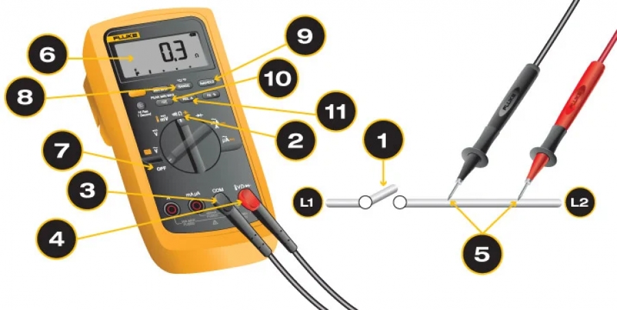
Fluke Indonesia - How to Measure Resistance with a Digital Multimeter
Resistance is measured using analog or digital multimeters. These tools also measure current, voltage, and more for various applications. Why measure resistance? To determine the condition of a circuit or component. The higher the resistance, the lower the current flow, and vice versa.
In general, the resistance of components used to control circuits (such as switches and relay contacts) starts out very low and increases over time due to factors such as wear and dirt. Loads such as motors and solenoids decrease in resistance over time due to insulation breakdown and moisture.
To measure resistance:
1. Turn power to circuit OFF.
- If a circuit includes a capacitor, discharge the capacitor before taking any resistance reading.
2. Turn digital multimeter dial to resistance, or ohms, which often shares a spot on the dial with one or more other test/measurement modes (continuity, capacitance or diode; see illustration below).
- The display should show OLΩ because, in Resistance mode, even before test leads are connected to a component, a digital multimeter automatically begins taking a resistance measurement.
- The MΩ symbol may appear in the display because the resistance of open (unattached) test leads is very high.
- When the leads are connected to a component, a digital multimeter automatically uses the Autorange mode to adjust to the best range.
- Pressing the Range button allows a technician to manually set the range.
- Best results will be achieved if the component to be tested is removed from the circuit. If the component is left in the circuit, the readings could be affected by other components in parallel with the component to be tested.
3. First insert the black test lead into the COM jack.
4. Then insert the red lead into the VΩ jack.
- When finished, remove the leads in reverse order: red first, then black.
5. Connect test leads across the component being tested.
- Make sure that contact between the test leads and circuit is good.
Tip: For very low-resistance measurements, use the relative mode (REL; see point 11). It may also be referred to as zero or Delta (Δ) mode. It automatically subtracts test lead resistance—typically 0.2 Ω to 0.5 Ω. Ideally, if test leads touch (are shorted together), the display should show 0 Ω.
Other factors that can affect resistance readings: Foreign substances (dirt, solder flux, oil), body contact with the metal ends of the test leads, or parallel circuit paths. The human body becomes a parallel resistance path, lowering total circuit resistance. Thus, avoid touching metal parts of test leads to avoid errors.
6. Read the measurement on the display.
7. When finished, turn the multimeter OFF to prevent battery drain.
8. Press the RANGE button to select a specific fixed measurement range.
- Be sure to note the annunciator (such as K or M) after the measurement in the display.
10. Press the MIN/MAX button to capture the lowest and highest measurement.
- The multimeter beeps each time a new reading is recorded.
- Measurements above and below the reference value are displayed.
Resistance Measurement Analysis
The significance of a resistance reading depends on the component being tested. In general, resistance of any one component varies over time and from component to component. Slight resistance changes are usually not critical but may indicate a pattern that should be noted. For example, as the resistance of a heating element rises, the current passing through the element decreases, and vice versa.
 Chatt kami sekarang!


CONTACT US
Phone : (021)29478974, (021)22997129
Mobile/WA: 0811 1388 063
Address: Ruko Concordia SRB26 Kota Wisata, Bogor 16968 Indonesia
Email : sales@ptbestinstrument.com
Who's Online
We have 114 guests and no members online